实现不同VLAN间的网络访问
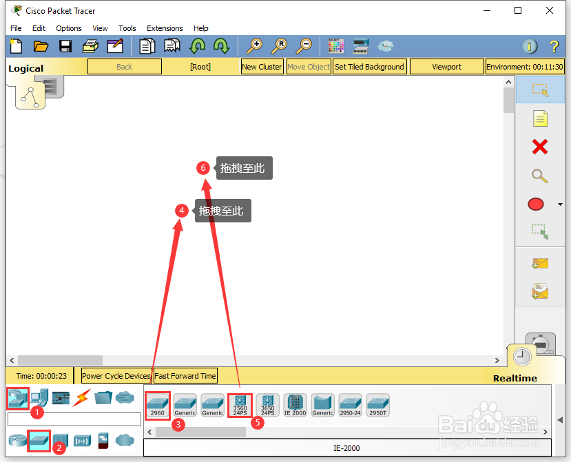
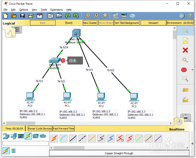
1、在Cisco Packet Tracer模拟器中,通过下方的设备选择区,选择【Network Devices】中的【Switches】里的【2960-24TT】、【3560-24PS】拖拽至工作区中;
添加完成后,在工作区中可以看到名称为【Swith0】的【2960-24TT】、【Multilayer Switch0】的【3560-24PS】设备;

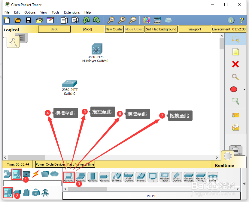
2、通过下方的设备选择区,选择【End Devices】中的【Generic】里的【PC-PT】拖拽至工作区中;
添加完成后,在工作区中可以看到4台名称分别为【PC0】、【PC1】、【PC2】、【PC3】的【PC-PT】设备;

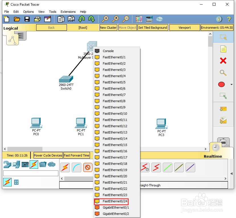
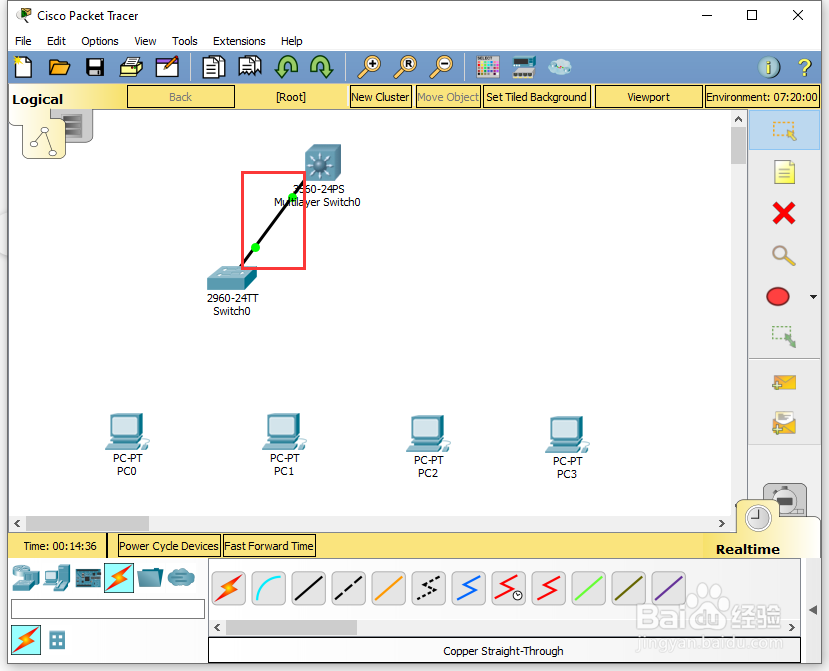
3、通过下方的设备选择区,选择【Connections】中的【Copper Straight-Through】,将工作区中的【Switch0】的【FastEthernet0/24】与【Multilayer Switch0】的【FastEthernet0/24】进行连接;

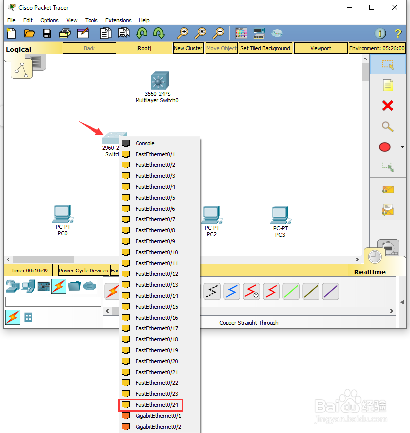
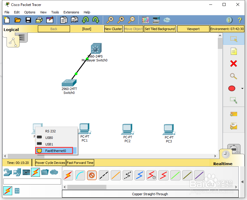
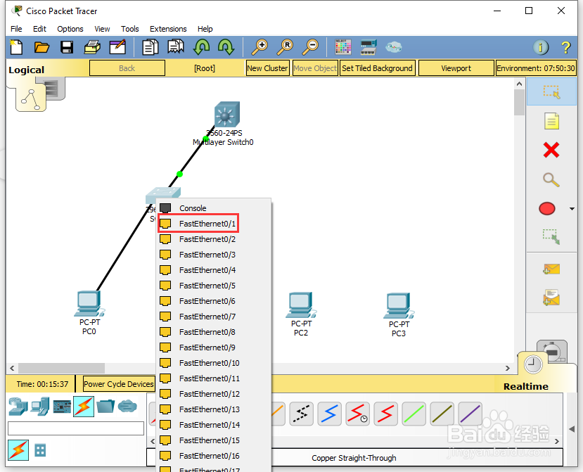
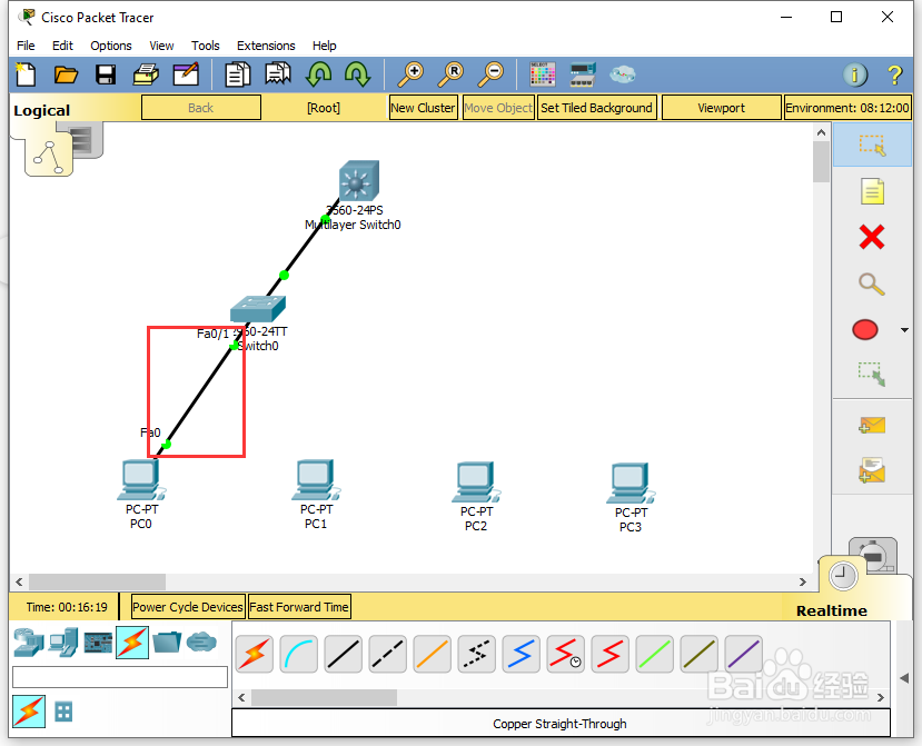
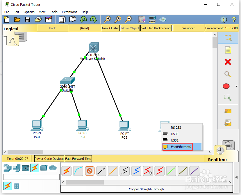
4、通过下方的设备选择区,选择【Connections】中的【Copper Straight-Through】,将工作区中的【PC0】的【FastEthernet0】与【Switch0】的【FastEthernet0/1】进行连接;

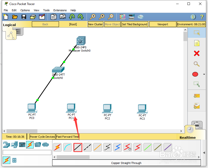
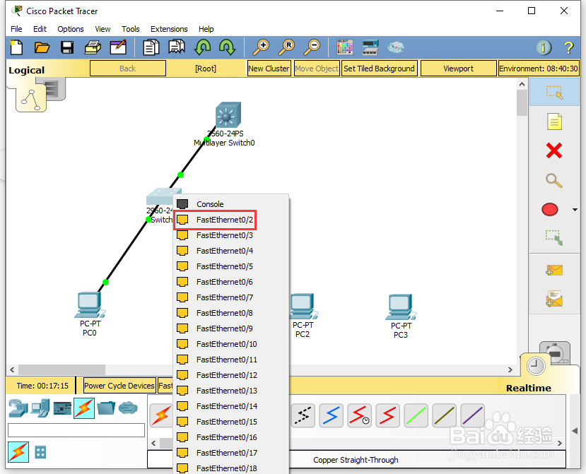
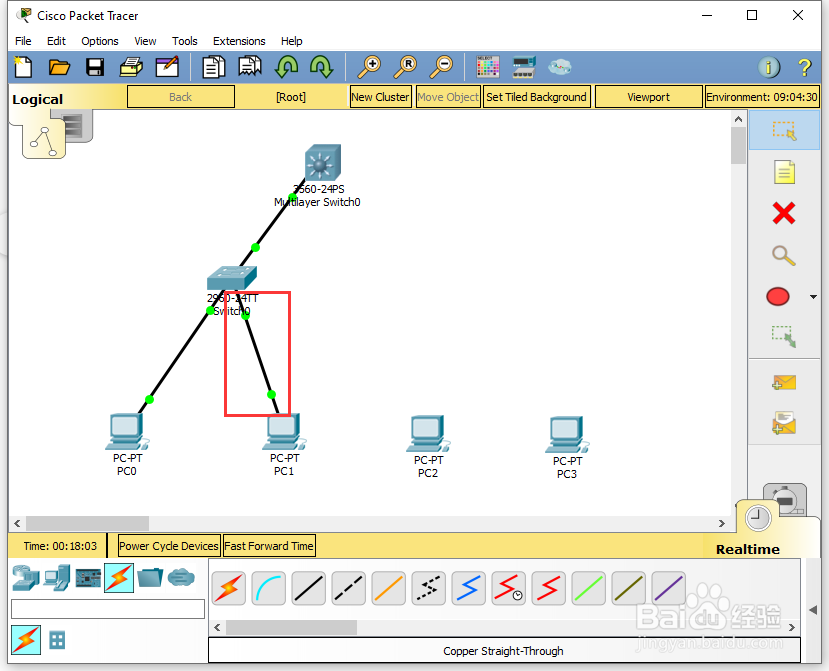
5、通过下方的设备选择区,选择【Connections】中的【Copper Straight-Through】,将工作区中的【PC1】的【FastEthernet0】与【Switch0】的【FastEthernet0/2】进行连接;

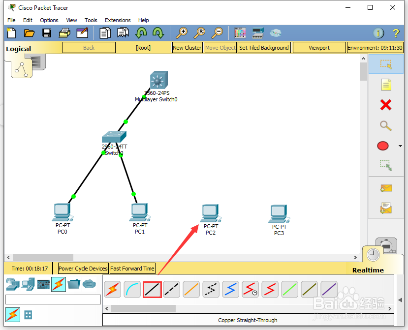
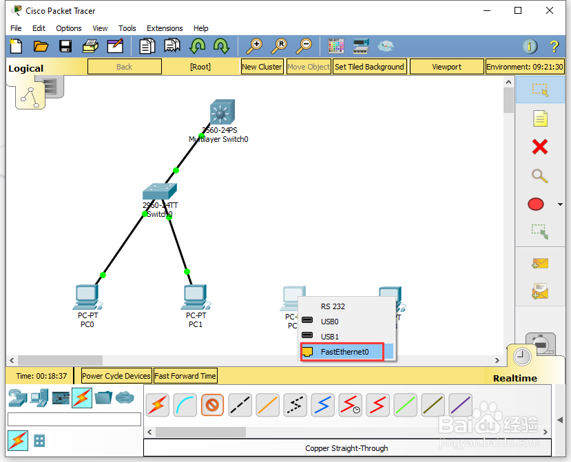
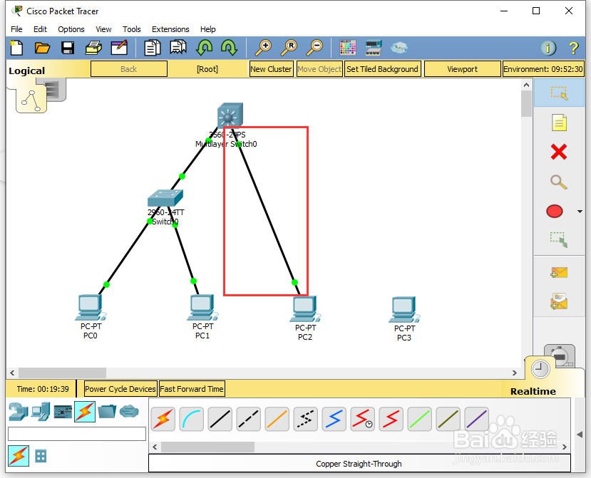
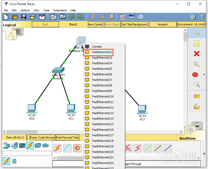
6、通过下方的设备选择区,选择【Connections】中的【Copper Straight-Through】,将工作区中的【PC2】的【FastEthernet0】与【Multilayer Switch0】的【FastEthernet0/1】进行连接;

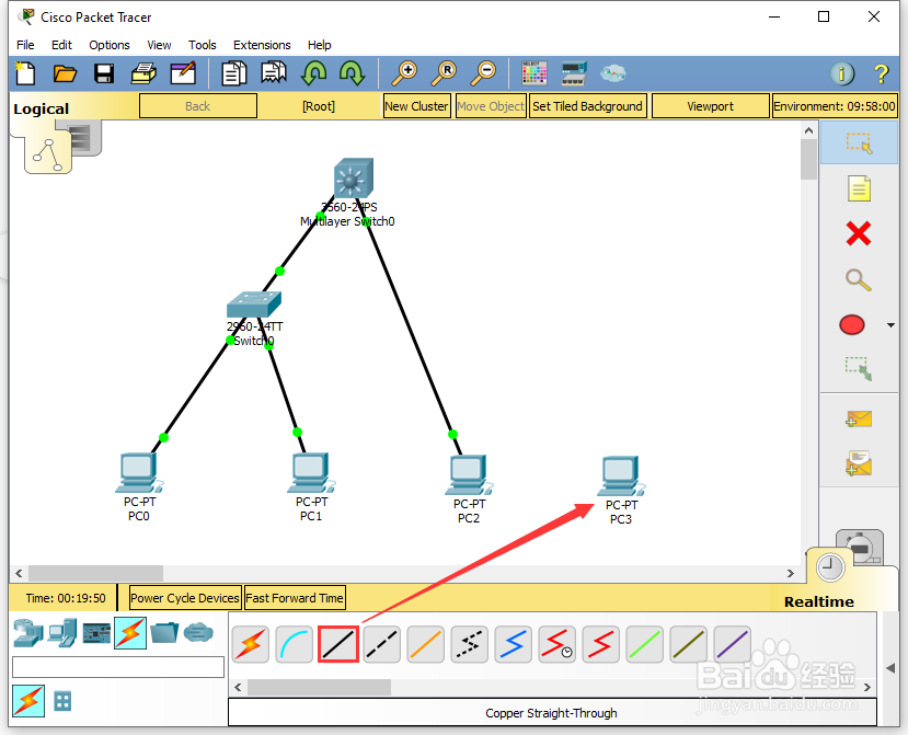
7、通过下方的设备选择区,选择【Connections】中的【Copper Straight-Through】,将工作区中的【PC3】的【FastEthernet0】与【Multilayer Switch0】的【FastEthernet0/2】进行连接;
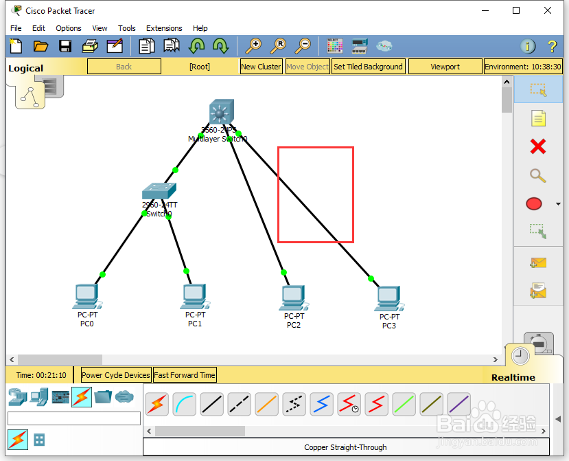
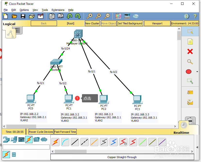
8、为了方便查看相关的设备信息,选择右侧的【Place Note (N)】,在工作区中对相应的设备进行注释;


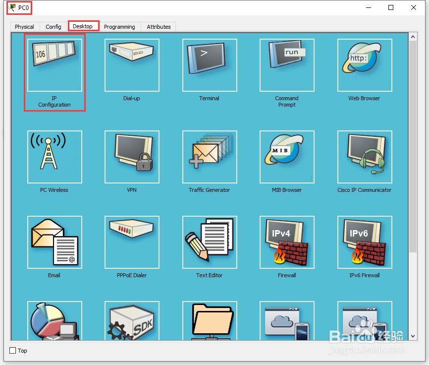
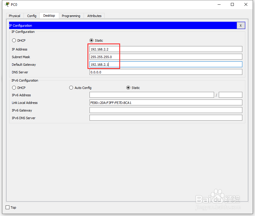
9、在工作区中,点击【PC0】,在PC0的配置界面,选择【Desktop】中的【IP Configuration】,在【IP Configuration】界面,进行IP的配置,【IP Address】为:192.168.2.2,【Subnet Mask】为:255.255.255.0,【Default Gateway】为:192.168.2.1;

10、在工作区中,点击【PC1】,在PC1的配置界面,选择【Desktop】中的【IP Configuration】,在【IP Configuration】界面,进行IP的配置,【IP Address】为:192.168.3.2,【Subnet Mask】为:255.255.255.0,【Default Gateway】为:192.168.3.1;


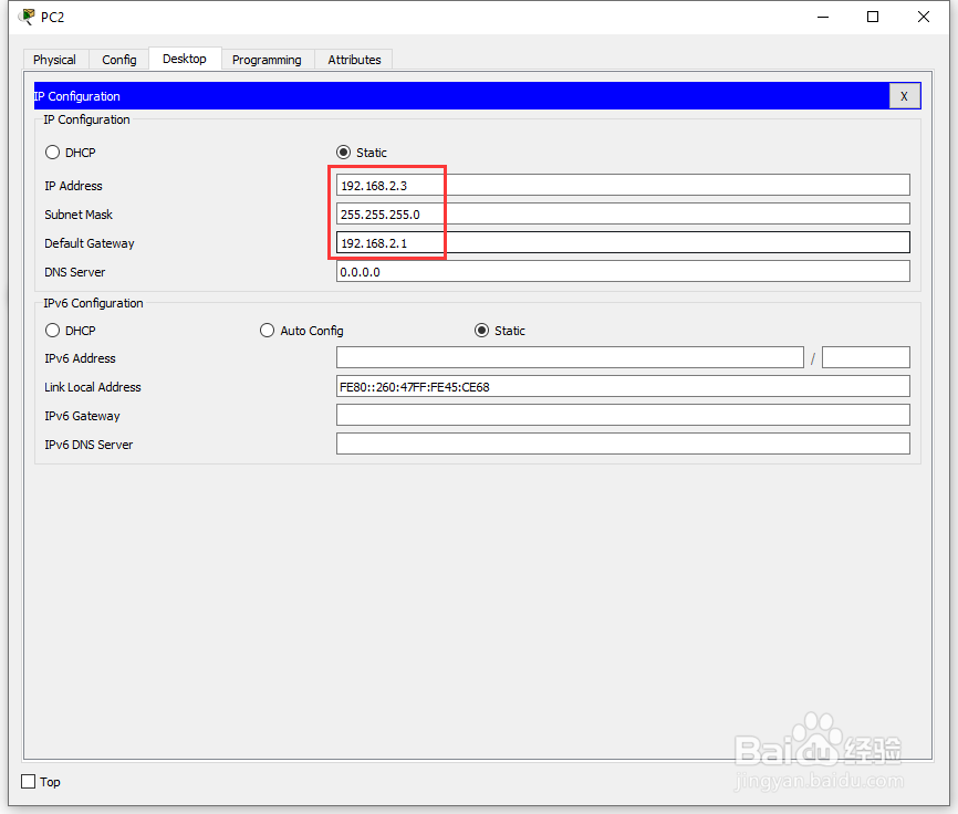
11、在工作区中,点击【PC2】,在PC2的配置界面,选择【Desktop】中的【IP Configuration】,在【IP Configuration】界面,进行IP的配置,【IP Address】为:192.168.2.3,【Subnet Mask】为:255.255.255.0,【Default Gateway】为:192.168.2.1;


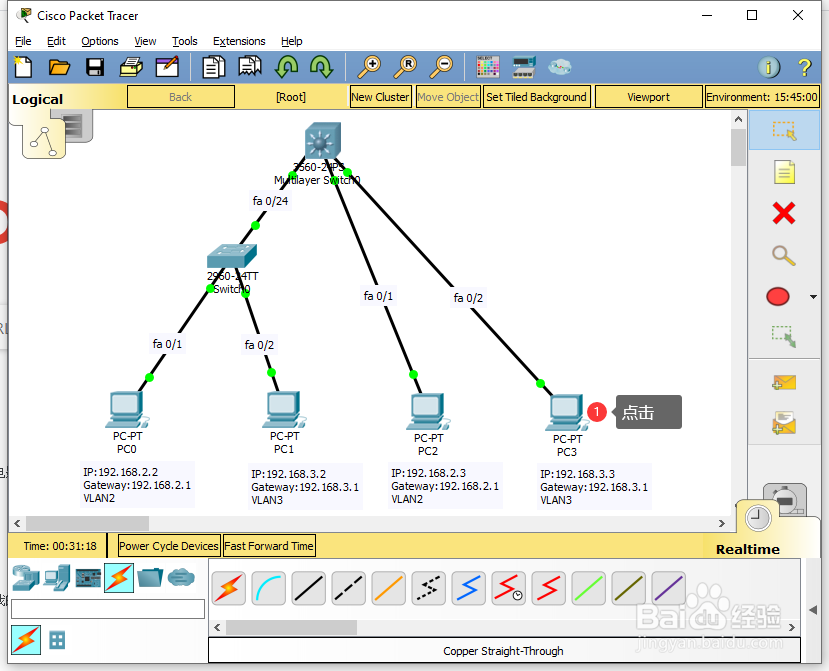
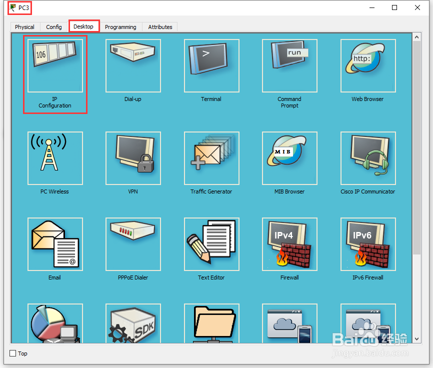
12、在工作区中,点击【PC3】,在PC3的配置界面,选择【Desktop】中的【IP Configuration】,在【IP Configuration】界面,进行IP的配置,【IP Address】为:192.168.3.3,【Subnet Mask】为:255.255.255.0,【Default Gateway】为:192.168.3.1;

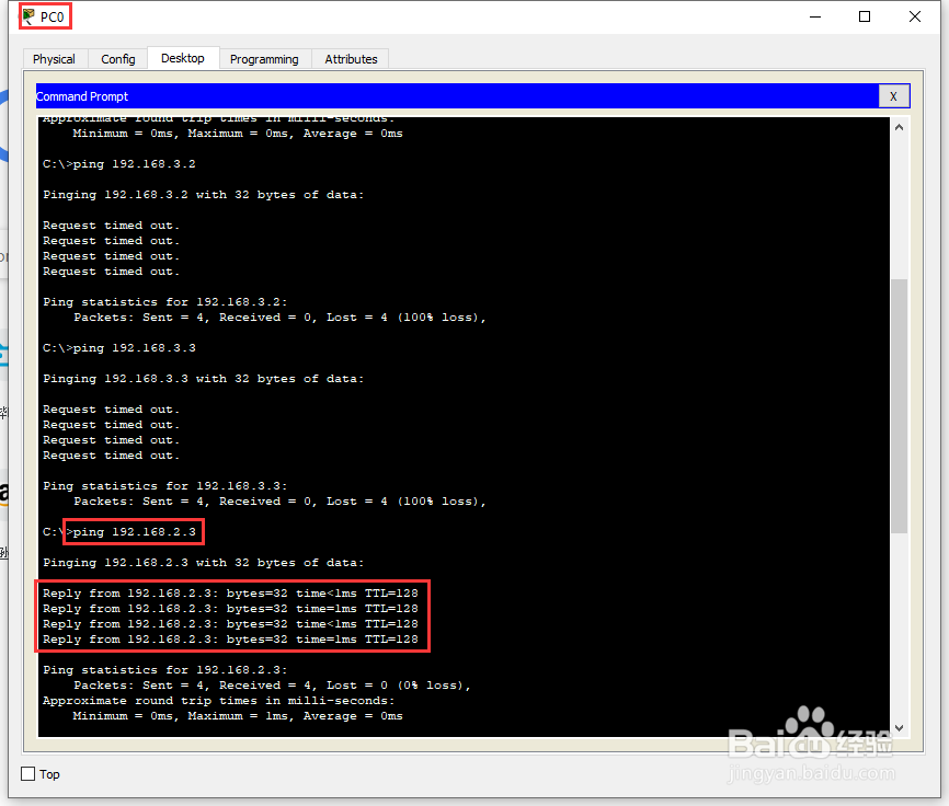
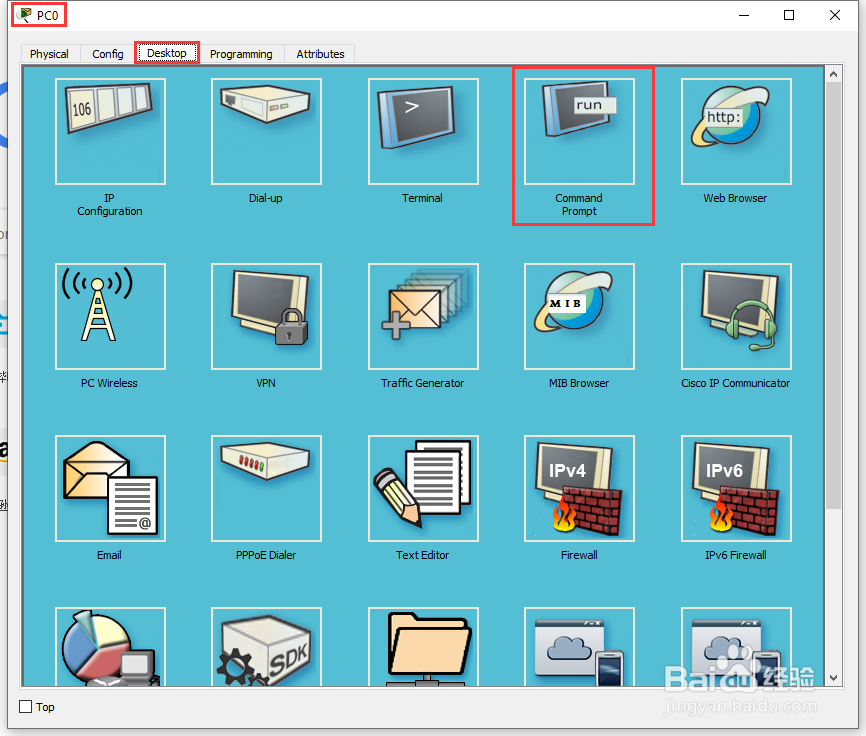
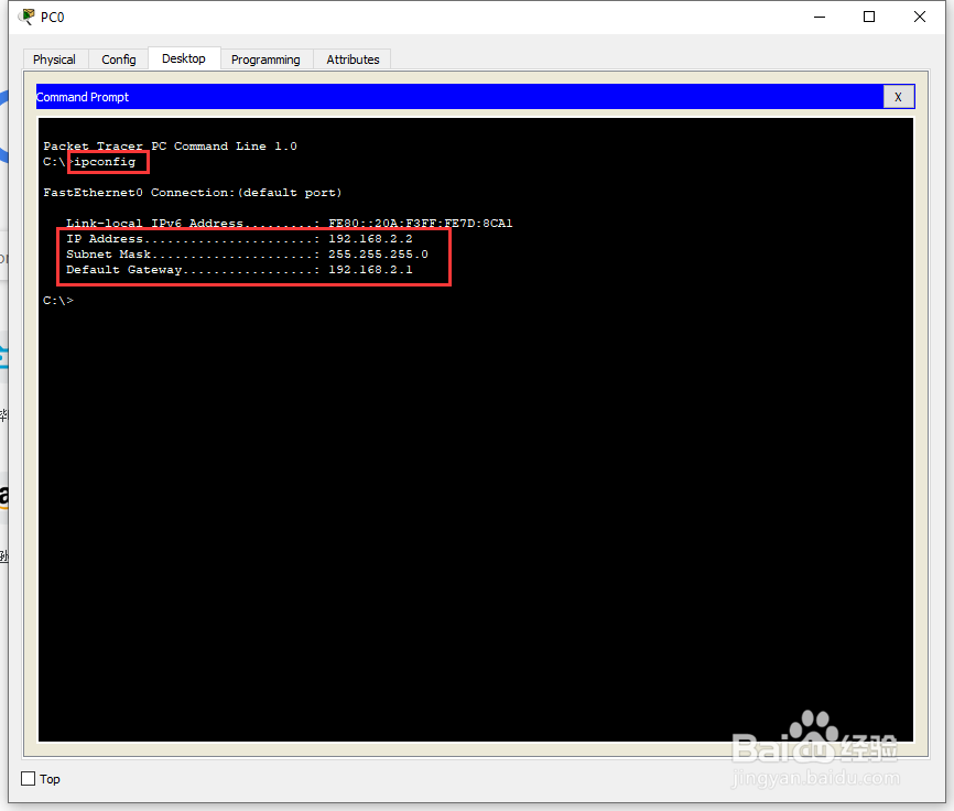
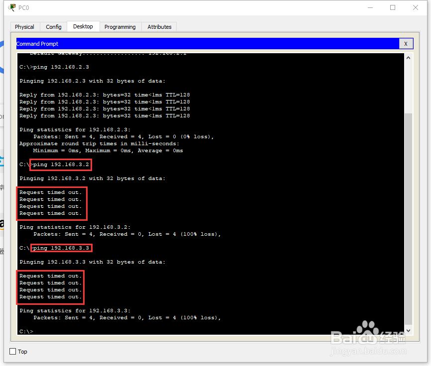
13、在工作区中,点击【PC0】,进入PC0的配置界面,选择【Desktop】中的【Command Prompt】,在【Command Prompt】输入【ipconfig】查看本机的ip信息,
输入【ping 192.168.2.3】查看PC0与PC2的网络连通性,结果为正常;
输入【ping 192.168.3.2】查看PC0与PC1的网络连通性,结果为超时;
输入【ping 192.168.3.3】查看PC0与PC3的网络连通性,结果为超时;
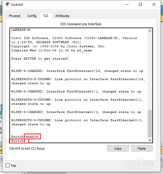
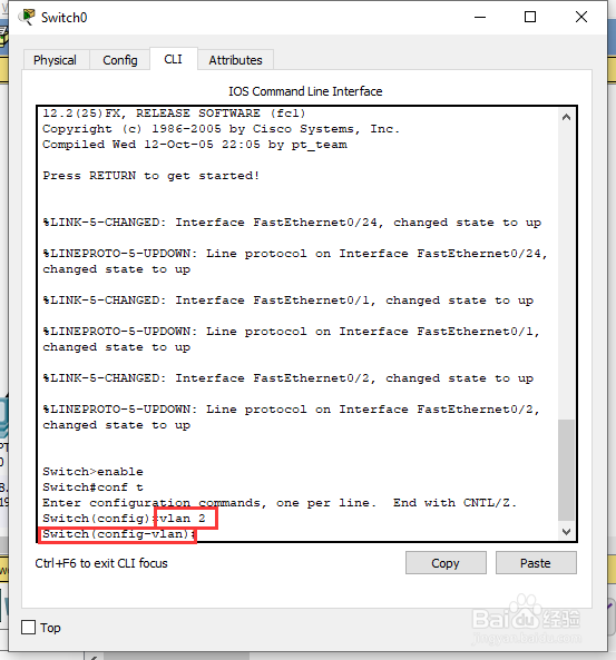
14、在工作区中,点击【Switch0】,在Switch0的配置界面选择【CLI】,在【CLI】界面,直接按回车,进入用户模式【Switch>】;
在用户模式【Switch>】中输入命令【enable】或【en】进入特权模式【Switch#】 ;
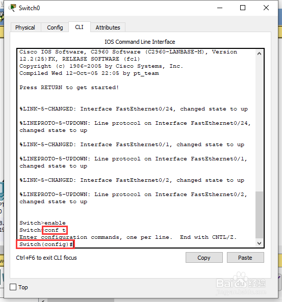
在特权模式【Switch#】中输入命令【configure terminal】或【conf t】进入全局配置模式【Switch(config)#】;

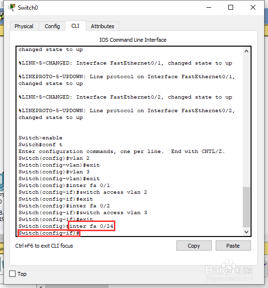
15、在全局配置模式【Switch(config)#】中输入命令【vlan 2】添加新的虚拟端口 vlan 2,并进入接口模式【Switch(config-vlan)#】;
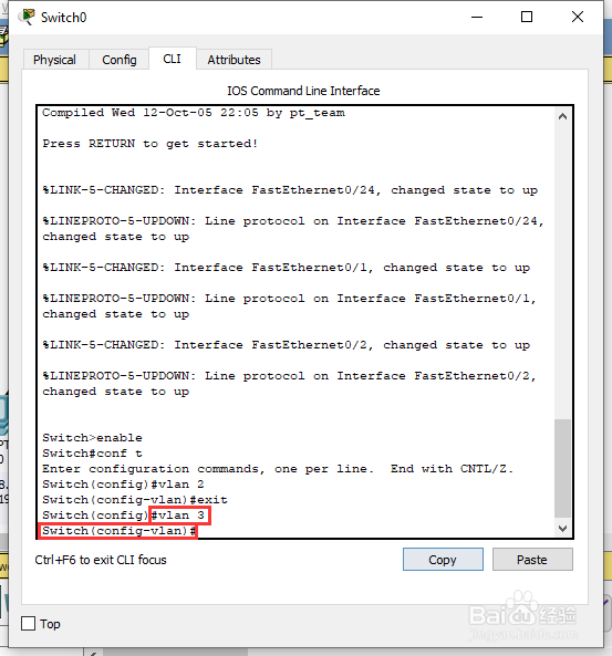
在接口模式【Switch(config-vlan)#】中输入命令【exit】返回到全局配置模式【Switch(config)#】;
在全局配置模式【Switch(config)#】中输入命令【vlan 3】添加新的虚拟端口 vlan 3,并进入接口模式【Switch(config-vlan)#】;
在接口模式【Switch(config-vlan)#】中输入命令【exit】返回到全局配置模式【Switch(config)#】;


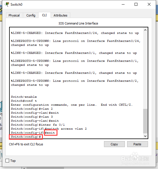
16、在全局配置模式【Switch(config)#】中输入命令【interface fa 0/1】切换到fa 0/1端口模式【Switch(config-if)#】;
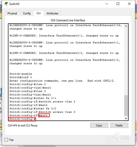
在端口模式【Switch(config-if)#】中输入命令【switch access vlan 2】将fa 0/1端口与vlan2进行绑定,接着输入命令【exit】返回到全局配置模式【Switch(config)#】;


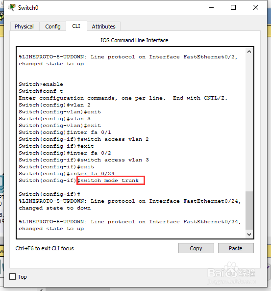
17、在全局配置模式【Switch(config)#】中输入命令【interface fa 0/24】切换到fa 0/24端口模式【Switch(config-if)#】;
在端口模式【Switch(config-if)#】中输入命令【switchport mode trunk】将fa 0/24端口连接模式更改为trunk,接着输入命令【end】返回到特权模式【Switch#】;
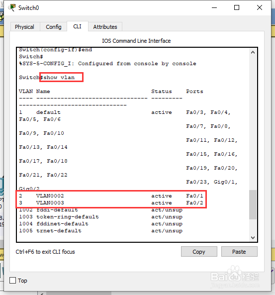
在特权模式【Switch#】中输入命令【show vlan】查看交换机的 vlan 配置信息;

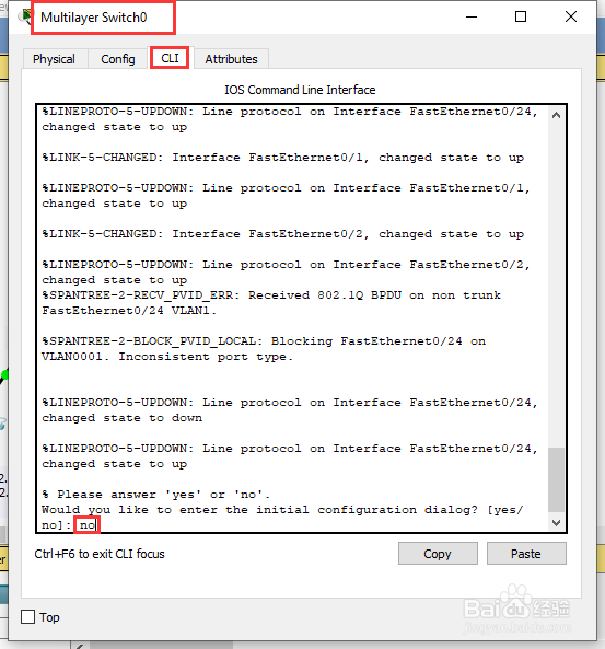
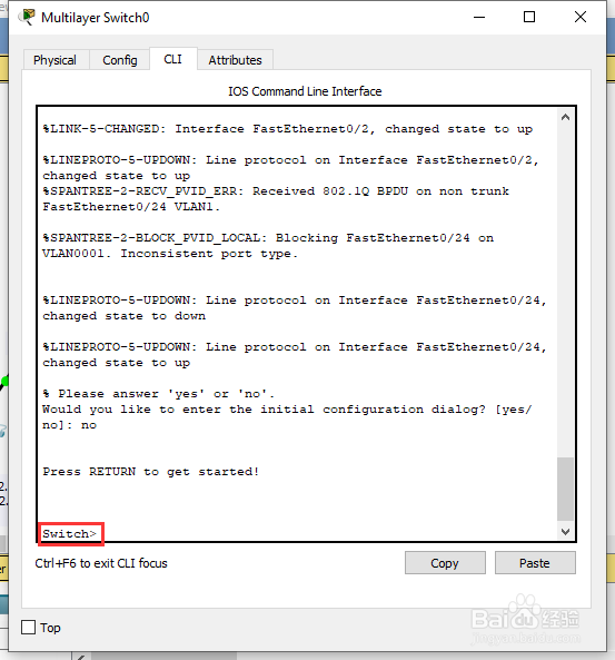
18、在工作区中,点击【Multilayer Switch0】,在Switch0的配置界面选择【CLI】,在【CLI】界面,直接按回车,在配置对话框中输入【no】,继续回车;
进入用户模式【Switch>】;

19、在用户模式【Switch>】中依次输入如下命令(//为说明内容,无需输入):
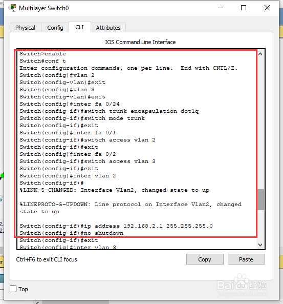
Switch>enable //进入特权模式
Switch#conf t //进入全局配置模式
Switch(config )#vlan 2 //添加新的vlan 2
Switch(config-vlan)#exit //返回全局配置模式
Switch(config )#vlan 3 //添加新的vlan 3
Switch(config-vlan)#exit //返回全局配置模式
Switch(config )#inter fa 0/24 //切换到fa 0/24端口
Switch(config-if)#switchport trunk encapsulation dot1q //给fa 0/1接口的trunk封装为802.1Q的帧格式
Switch(config-if)#switchport mode trunk //定义fa 0/24接口的工作模式为trunk
Switch(config-if)#exit //返回全局配置模式
Switch(config )#inter fa 0/2 //切换到fa 0/2端口
Switch(config-if)#switchport access vlan 2 //将fa 0/2端口绑定到vlan2
Switch(config-if)#exit //返回全局配置模式
Switch(config )#inter fa 0/3 //切换到fa 0/3端口
Switch(config-if)#switchport access vlan 3 //将fa 0/3端口绑定到vlan3
Switch(config-if)#exit //返回全局配置模式
Switch(config )#int vlan 2 //进入vlan2虚拟接口
Switch(config-if)#ip address 192.168.1.1 255.255.255.0 //配置IP地址
Switch(config-if)#no shutdown //开启该三层端口(路由功能)
Switch(config-if)#exit //返回全局配置模式
Switch(config )#int vlan 3 //进入vlan2虚拟接口
Switch(config-if)#ip address 192.168.2.1 255.255.255.0 //配置IP地址
Switch(config-if)#no shutdown //开启该三层端口(路由功能)
Switch(config-if)#end //结束配置,返回特权模式
Switch#conf t //进入全局配置模式
Switch(config)#ip routing //启动IP路由
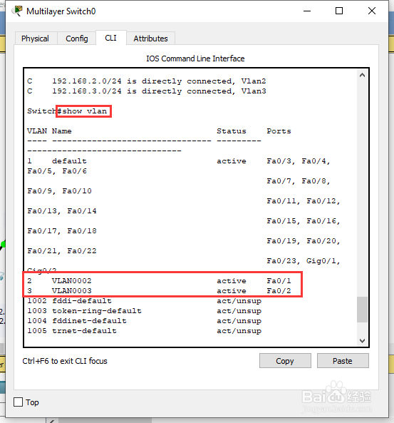
Switch#show ip route //显示路由表
Switch#show vlan //显示vlan信息


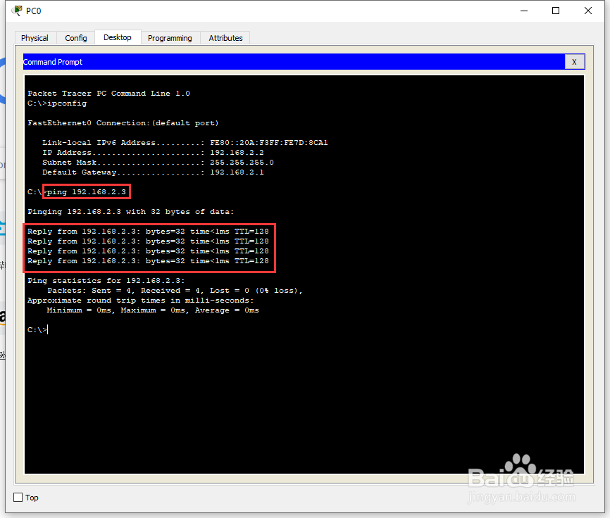
20、在工作区中,点击【PC0】,进入PC0的配置界面,选择【Desktop】中的【Command Prompt】,在【Command Prompt】中,
输入【ping 192.168.2.3】查看PC0与PC2的网络连通性,结果为正常;
输入【ping 192.168.3.2】查看PC0与PC1的网络连通性,结果为正常;
输入【ping 192.168.3.3】查看PC0与PC3的网络连通性,结果为正常。